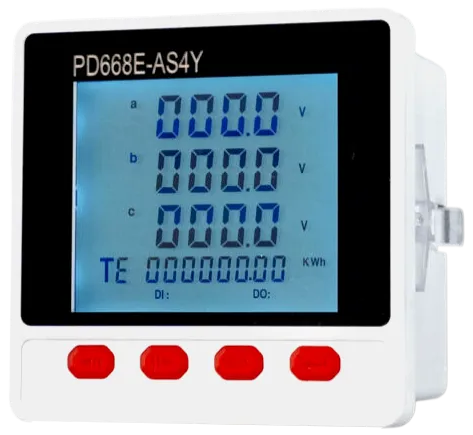
PD668E-AS4Y Digital Display Meter
Three-phase Phase Voltage: UA, UB, UC\nThree-phase Line Voltage: UAB, UBC, UCA\nThree-phase Current: IA, IB, IC\nActive Power: Per-phase active power and total active power\nReactive Power: Per-phase reactive power and total reactive power\nApparent Power: Per-phase apparent power and total apparent power\nPower Factor: Per-phase power factor and total power factor\n2-channel Energy Pulse Output\nCommunication Output: RS485\n\nLeft Key: In programming mode, used to scroll up menu items when selecting menu items; used to decrease parameter value when modifying parameter values; in measurement display state, press this key to scroll up the display interface.\nRight Key: In programming mode, used to scroll down menu items when selecting menu items; used to increase parameter value when modifying parameter values; in measurement display state, press this key to scroll down the display interface.\nMenu Key: In measurement display state, press this key to enter programming mode. The meter prompts for password input (CodE). The initial password is 0001. After entering the correct password, the meter can be programmed and set; in programming mode, it is used to return to the previous menu.\nConfirm Key: In programming mode, confirm after selection and return to the previous menu.\nPress the Left Key and Right Key to view electric quantity information on different pages.\nIf the page display value diSP is set to 0, each page is automatically cyclically displayed.\nSet the display mode: change from diSP=1 (three-phase current value) to diSP=4 (three-phase power factor value).\nChange the input signal network from three-phase four-wire to three-phase three-wire, input voltage 10KV/100V, input current 300A/5A.\nModify meter communication parameters: meter address code is 10, baud rate is 9600, data format is 8 data bits, 1 stop bit, even parity mode.\n\nPower Supply: The meter working power supply voltage range is AC/DC 85~264V. To prevent damage to the meter, it is recommended to install a 1A fuse on the live wire side when using AC power. In areas with poor power quality, it is recommended to install a surge suppressor and a fast pulse group suppressor in the power circuit.\n\nElectric Signal Input (Current Input and Voltage Input): Current input is A, B, C three-phase AC current signal input terminals, where I* is the current incoming line terminal; voltage input is A, B, C three-phase AC voltage signal input terminals. When wiring, please ensure that the phase sequence and polarity of the input signal correspond one-to-one with the terminals. The input voltage should not be higher than the rated input voltage of the product, otherwise the use of PT should be considered, and a 1A fuse must be installed at the voltage input terminal; the input current should not be higher than the rated input current of the product, otherwise the use of external CT should be considered. The input network nEt set in meter wiring and meter programming should be consistent with the wiring method of the measured load.\n\nEnergy Pulse Output: P+ is the active energy pulse output + terminal, Q+ is the reactive energy pulse output + terminal, P-Q- is the active/reactive energy pulse output - terminal. The output mode is open-collector optocoupler output, open-collector voltage VCC≤48V, current Iz≤50mA. The energy pulse output corresponds to secondary side data. When calculating the primary side energy, it needs to be multiplied by the voltage transformer ratio PT and current transformer ratio CT to obtain the primary side data.\n\nRS485 Communication Wiring: The meter provides an RS485 communication interface, adopting MODBUS_RTU communication protocol (see appendix). Up to 32 meters can be connected simultaneously on one communication line, and each meter should be set with a unique communication address within the line. The communication connection should use shielded twisted pair with copper mesh, with a wire diameter of not less than 0.5mm. When wiring, the communication line should be kept away from strong current cables or other strong electric field environments. The maximum transmission distance is 1200 meters. Typical network connection methods are shown in the figure below. Users can choose other suitable connection methods according to specific circumstances.\n\nSwitch Input (DI Input): DI1~DI4 are 1~4-channel passive dry contact input terminals. The meter has a built-in +5V power supply.\n\nSwitch Output (Do1~Do4) or Analog Transducer Output (Ao1~Ao4): The meter can support 4-channel switch output or 4-channel analog transducer output (corresponding function modules need to be installed).\n\nAddress Code: The address code is the 1st byte of each communication information frame, from 1 to 247. Each slave must have a unique address code, and only the slave whose address code matches the address code sent by the host can respond with feedback information. When the slave returns information, the returned data begins with its own address code. The address code sent by the host indicates the slave address to which it will be sent, while the address code returned by the slave indicates the returning slave address. The corresponding address code indicates where the information comes from.\n\nFunction Code: The 2nd byte of each communication information frame. The host sends, through the function code to tell the slave what action should be performed. The slave responds, the function code returned by the slave is the same as the function code sent from the host, indicating that the slave has responded to the host and has performed the related operation. The meter supports the following function codes: Function Code Definition Operation 03H Read Register Obtain the current binary value of one or more registers.\n\nData Area: The data area varies with the function code. These data can be numerical values, reference addresses, etc. For different slaves, the addresses and data information are different (a communication information table should be provided). The host uses communication commands (function code 03H) to freely read and modify the meter data registers. The length of data read at one time should not exceed the valid range of the data register address.\n\nPreset a 16-bit register (hexadecimal, all 1s), called the CRC register;\nXOR the 8 bits of the first byte of the data frame with the low byte in the CRC register, and store the result back into the CRC register.\nShift the CRC register one bit to the right, fill the highest bit with 0, and shift the lowest bit out for detection.\nIf the bit shifted out in the previous step is 0: repeat step 3 (next time); if 1: XOR the CRC register with a preset fixed value (0xA001);\nRepeat steps 3 and 4 until 8 shifts have been performed, thus completing the processing of a complete 8 bits;\nRepeat steps 2 through 5 to process the next 8 bits until all bytes are processed;\nThe value of the final CRC register is the CRC value.\n\nSign Bit: SIGN=0 is positive, SIGN=1 is negative;\nExponent Part: E = Exponent Part - 126;\nMantissa Part: M = Mantissa Part with the highest bit set to 1;\nData Result: REAL = SIGN × 2^E × M / (256 × 65536).\n\nExample: The host reads the energy data. From the address table, it can be known that the energy (positive active absorption) address is: (byte mode, compatible with old standard) 92 (005CH), length is 4 (0004H).\nHost: 01H 04H 00 5CH 00 04H 31 DBH\nSlave: 01 04H 04H 50 80 00 00H EBH 6CH\nAmong them, 50 80 00 00 is the active energy (absorption) data, EBH, 6CH are the low and high bits of CRC16.\nIts value: SIGN (sign bit = 0, positive), exponent EX = A1H - 126 = 35, mantissa: 80 00 00H\nResult: 2^35 × 80 00 00H / 100 00 00H = 17179869184 Wh = 17179869 kWh
Key Features
- Brand: Huabang
- Category: Digital Display Meter Series
- Model: PD668E-AS4Y
- 参数:值时用于将
- 参数:值递减;在测量显示状态下,按此键可将显示界面向上翻页。 右移键:在编程模式下,在选择菜单项目时用于菜单项目向下翻页;在修改
- 参数:值递增;在测量显示状态下,按此键可将显示界面向下翻页。 菜单键:测量显示状态下,按该键进入编程模式,仪表提示输入密码(CodE),初始密码为0001;输入正确的密码后,可对仪表进行编程、设置;编程模式下,用于返回上一菜单的作用。 确定键:在编程模式下,选择后确认,并返回到上次菜单。 按左移键和右移键