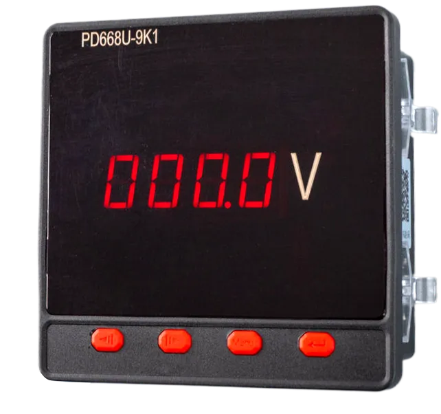
PD668U-9K1 Digital Display Meter
1.1 Single-phase AC Voltmeter Measurement Range: AC 0~400V\n1.2 Single-phase AC Ammeter Measurement Range: AC 0~5A\n1.3 Sensor-specific Meter (Voltage) Measurement Range: 0~9999V\n1.4 Sensor-specific Meter (Current) Measurement Range: 0~9999A\n1.5 Sensor-specific Meter (Frequency) Measurement Range: 0~9999Hz\n2.1 Three-phase AC Voltmeter Measurement Range: AC 0~400V\n2.2 Three-phase AC Ammeter Measurement Range: AC 0~5A\nSignal Input: DC 0/4~20mA or DC 0~5/10V Signal Input: DC 0/4~20mA or DC 0~5/10V Signal Input: DC 0/4~20mA or DC 0~5/10V\n\nConfirm Key: In programming mode, used to enter the menu when selecting a menu item.\nDecrease Key: In programming mode, used to scroll up at the same menu level when selecting a menu item, and decrease the current digit value by 1 when setting data.\nIncrease Key: In programming mode, used to scroll down at the same menu level when selecting a menu item, and increase the current digit value by 1 when setting data.\nMenu Key: In measurement display state, long press this key for 3 seconds to enter programming mode. The meter will prompt for password input (Pro 9). The initial password is 0001. After the password is entered correctly, the meter can be set.\n\nPower Supply: The meter working power supply voltage range is AC 176-264V or AC/DC 85-265V. To prevent damage to the meter, it is recommended to install a 1A fuse on the live wire side when using AC power. In areas with poor power quality, it is recommended to install a surge suppressor and a fast pulse group suppressor in the power circuit.\n\nElectric Signal Input (Current Input and Voltage Input): Current input is A, B, C three-phase AC current signal input terminals, where I* is the current incoming line terminal; voltage input is A, B, C three-phase AC voltage signal input terminals. When wiring, please ensure that the phase sequence and polarity of the input signal correspond one-to-one with the terminals. The input voltage should not be higher than the rated input voltage of the product, otherwise the use of PT should be considered, and a 1A fuse must be installed at the voltage input terminal; the input current should not be higher than the rated input current of the product, otherwise the use of external CT should be considered.\n\nRS485 Communication Wiring: The meter provides an RS485 communication interface, adopting MODBUS_RTU communication protocol (see appendix). Up to 32 meters can be connected simultaneously on one communication line, and each meter should be set with a unique communication address within the line. The communication connection should use shielded twisted pair with copper mesh, with a wire diameter of not less than 0.5mm. When wiring, the communication line should be kept away from strong current cables or other strong electric field environments. Users can choose other suitable connection methods according to specific circumstances.\n\nAddress Code: The address code is the 1st byte of each communication information frame, from 1 to 247. Each slave must have a unique address code, and only the slave whose address code matches the address code sent by the host can respond. When the slave sends information, the data starts with its own address code. The address code sent by the host indicates the slave address to which it will be sent, and the address code returned by the slave indicates the returning slave address. The corresponding address code indicates where the information comes from.\n\nFunction Code: The 2nd byte of each communication information frame. The host sends, through the function code to tell the slave what action should be performed. The slave responds, and the function code returned by the slave is the same as the function code sent from the host, indicating that the slave has responded to the host and has performed the related operation. The meter supports the following function codes: Function Code Definition Operation 03H Read Register Obtain the current binary value of one or multiple registers.\n\nData: The data area varies with the function code. These data can be numerical values, reference addresses, etc. For different slaves, the addresses and data information are different (a communication information table should be provided). The host uses communication commands (function code 03H) to freely read and modify the meter data registers. The length of data read at one time should not exceed the valid range of the data register address.\n\nPreset a 16-bit register (hexadecimal, all 1s), called the CRC register;\nXOR the 8 bits of the first byte of the data frame with the low byte in the CRC register, and store the result in the CRC register.\nShift the CRC register one bit to the right, fill the highest bit with 0, and shift the lowest bit out for detection.\nIf the bit shifted out in the previous step is 0: repeat step 3 (next time); if 1: XOR the CRC register with a preset fixed value (0xA001);\nRepeat steps 3 and 4 until 8 shifts have been performed, thus completing the processing of a complete 8 bits;\nRepeat steps 2 through 5 to process the next 8 bits until all bytes are processed;\nThe value of the final CRC register is the CRC value.\n\nQuery Data Frame (Host): Address Command Starting Register Address (High) Starting Register Address (Low) Number of Registers (High) Number of Registers (Low) CRC16 (Low) CRC16 (High) 01H 03H 00H 00H 00H 01H 84H 0AH\nResponse Data Frame (Host): Address Command Data Length Data (6 bytes) CRC16 (Low) CRC16 (High) 01H 03H 02H 13H, 88H B5H 12H\n\nThree-phase Digital Voltmeter: Address Item Description Data Type Attribute Description 0 A-phase voltage value int R Secondary side value 1 B-phase voltage value int R Secondary side value 2 C-phase voltage value int R Secondary side value 3 Pt voltage ratio int R/W 1~9999\n\nThree-phase Digital Ammeter: Address Item Description Data Type Attribute Description 0 A-phase current value int R Secondary side value 1 B-phase current value int R Secondary side value 2 C-phase current value int R Secondary side value 3 Ct current ratio int R/W 1~9999\n\nNote: The read voltage and current values are secondary side values. Actual primary voltage = (read voltage value × PT) / 10V. For example, if the read voltage value is 1000 and PT=100, then the current actual voltage value is 10000V = 10.00 kV. Actual primary current = (read current value × CT) / 1000A. For example, if the read current value is 5000 and CT=20, then the current actual current value is 100.0A
Key Features
- Brand: Huabang
- Category: Digital Display Meter Series
- Model: PD668U-9K1
- 接线:时请保证输入信号的相序、极性与端子一一对应。输入电压应不高于产品的额定输入电压, 否则应考虑使用PT, 在电压输入端须安装1 A保险丝; 输入电流应不高于产品的额定输入电流, 否则应考虑使用外部CT。 RS 485通讯
- 接线:仪表提供一个RS 485通讯接口, 采用MODBUS_RTU通讯规约(见附录)。在一条通讯线路上最多可以同时连接32台仪表, 每台仪表应设置线路内唯一的通讯地址。通讯连接应使用带有铜网的屏蔽双绞线,线径不小于0 . 5 mm。布线时应使通讯线远离强电电缆或其他强电场环境, 用户可根据具体情况选用其他
- 功能:码 每个通讯信息帧的第2字节。主机发送,通过